Design for Manufacturing (DFM)

Improve Manufacturability Before CNC Production Begins.

Engineering Review for More Practical, Production-Ready CNC Components.

Gulf Precision Works supports Design for Manufacturing review for CNC-machined components by evaluating geometry, tool access, tolerances, material considerations and other manufacturability factors before machining begins, helping customers refine designs for prototype and production requirements across the UAE and wider Gulf region.

Geometry Review Features & machining access
Tolerance Review Critical dimensions
Material Review Grade & machinability
Process Planning Milling, turning & setups
Production Readiness Prototype to repeat manufacture
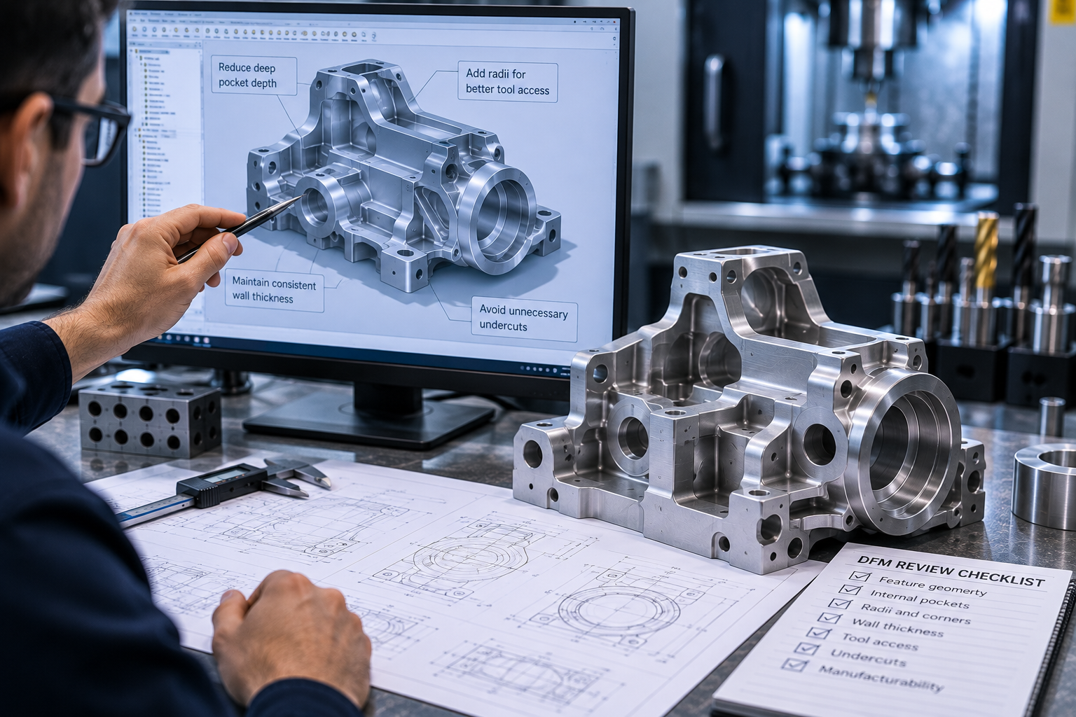
Engineer reviewing CAD geometry and a CNC-machined component during design for manufacturing analysis
DFM Connects Design Intent With Manufacturing Reality Reviewing the component before machining can help identify practical manufacturing considerations while the design is still easier to refine.

What DFM Means in CNC Manufacturing

Review the Design Before Committing It to the Machine.

Design for Manufacturing focuses on whether a component can be produced practically using the intended machining process.

A DFM review can consider geometry, machining access, internal features, tolerances, material selection, setups, inspection needs and other manufacturing factors before production begins. The objective is not to change the engineering intent, but to identify areas that may benefit from clarification or refinement for CNC manufacture.

01 Design

Start with the latest CAD model, drawing and functional requirement.

02 Review

Evaluate geometry, access, tolerances, material and machining considerations.

03 Refine

Clarify or update features where the engineering team considers it appropriate.

04 Manufacture

Proceed with a clearer, more manufacturing-ready component definition.

DFM Supports Engineering Decisions — It Does Not Replace Them

Final design responsibility, material selection and functional approval remain with the customer's engineering authority. DFM feedback should be reviewed against the component's intended function and project requirements.

DFM Review Areas

Six Areas That Can Influence CNC Manufacturability.

A DFM review looks beyond the overall component shape. Individual features, machining access, dimensional requirements, workholding and process strategy can all influence how practically a component can be manufactured.
CAD geometry and CNC-machined component reviewed for design for manufacturing
01 · Geometry

Geometry & Feature Design

Review pockets, radii, bosses, undercuts, internal geometry and feature relationships that can influence machining strategy.

CNC cutting tool access review for deep pockets and complex component geometry
02 · Tool Access

Tool Access & Reach

Evaluate whether cutting tools can reach required surfaces without excessive tool length or difficult machining conditions.
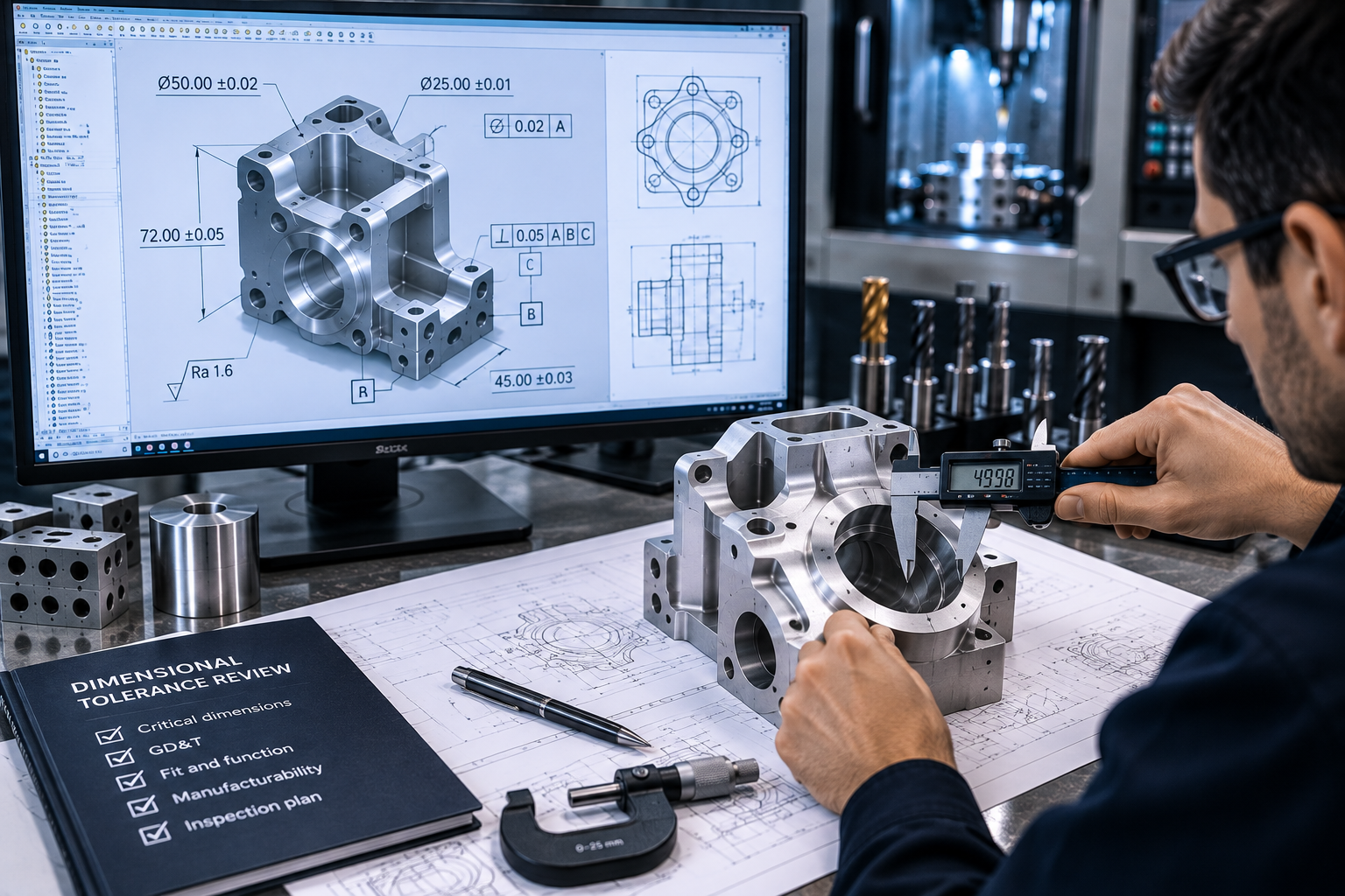
Engineer reviewing critical dimensions and tolerances on a CNC component drawing
03 · Tolerances

Tolerances & Critical Dimensions

Identify dimensions that directly affect fit, function or assembly instead of applying unnecessary tight tolerances everywhere.

Thin wall CNC-machined component reviewed for wall thickness and structural manufacturability
04 · Structure

Wall Thickness & Structural Features

Thin walls, deep pockets and unsupported features may require additional consideration for rigidity, machining sequence and workholding.
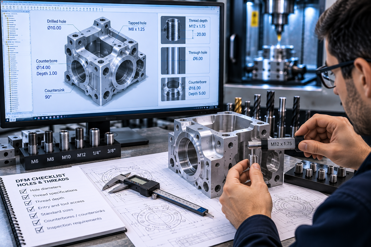
CNC component holes threads and internal features reviewed for manufacturability
05 · Features

Holes, Threads & Internal Features

Review hole depth, diameter, thread requirements, entry conditions and accessibility for practical CNC manufacture and inspection.
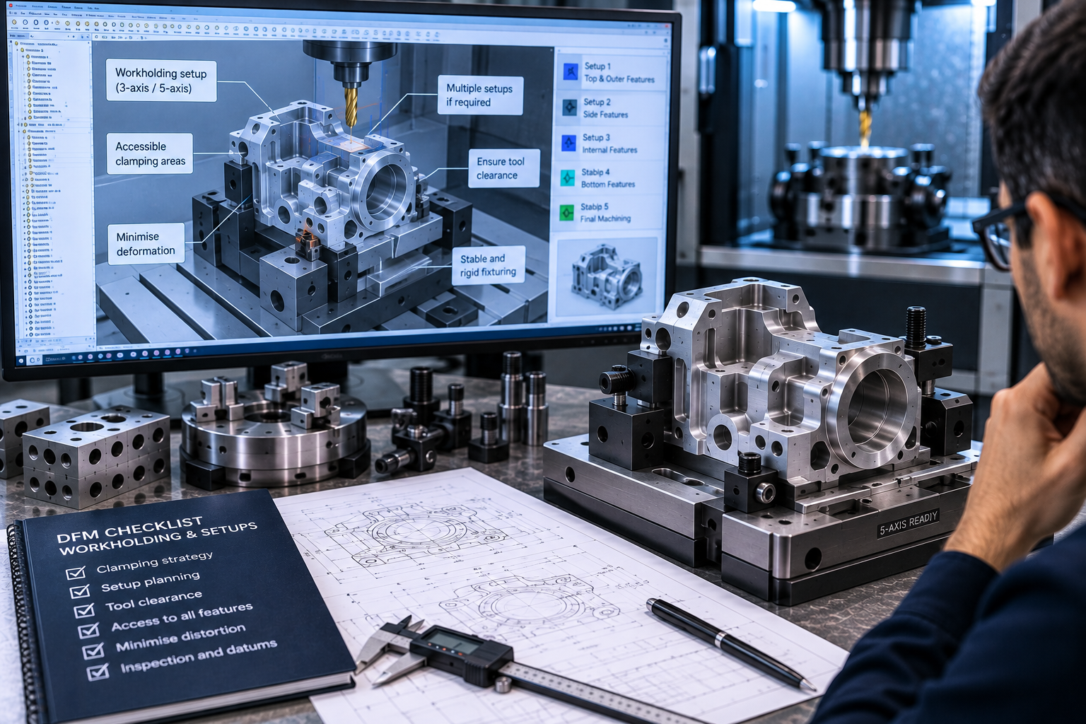
CNC fixture and workholding strategy reviewed for machining setups
06 · Machining Strategy

Workholding, Setups & Process Planning

Consider how the component can be located, supported and accessed across the required machining operations.

Input Latest CAD & Drawing
Review Manufacturing Considerations
Feedback Engineering Clarifications
Outcome Clearer Manufacturing Definition
Engineer reviewing CNC geometry tool access deep pockets radii and machining reach on a complex component
Good Geometry Supports Practical Tool Access Internal corners, pocket depth, undercuts and feature orientation can directly influence the cutting tools, setups and machining strategy required.

Geometry & Tool Access

Design Features Around How They Can Actually Be Machined.

A component may look straightforward in CAD but still present difficult machining conditions. Deep cavities, sharp internal corners, inaccessible surfaces, undercuts and long tool reach can influence tool selection, rigidity, setup strategy and manufacturing practicality.

Geometry Review Checklist DFM Considerations
01
Internal Corner Radii

Internal corners should account for the physical radius of the cutting tool where a sharp corner is not functionally required.

02
Pocket Depth & Tool Reach

Deep cavities may require longer tools, which can influence rigidity, access and the overall machining approach.

03
Undercuts & Hidden Surfaces

Features that cannot be accessed directly may require specialised tooling, additional setups or alternative feature definition.

04
Feature Orientation

Orienting related features around practical machining directions can influence the number of required setups and access conditions.

05
Tool & Holder Clearance

Access should consider not only the cutter but also the tool holder and surrounding component geometry.

Risk Restricted Access
Review Tool & Feature Geometry
Outcome Practical Machining Strategy
Functional Requirements Still Come First

DFM does not mean simplifying every difficult feature. Where a feature is essential to fit, function or performance, the engineering requirement should remain the priority and the machining strategy should be reviewed around it.

Tolerance & Feature Review

Apply Tight Tolerances Where They Serve a Functional Purpose.

Tolerances influence machining strategy, inspection, process control and component cost. A DFM review helps distinguish genuinely critical features from dimensions that may not require the same level of control.

Tolerance Review Logic

Start With Fit, Function and Assembly

The drawing should communicate which features matter most to component performance. DFM review can help identify where tolerance requirements need clarification before machining and inspection planning begin.

01
Identify Critical Features Determine which dimensions directly influence fit, function, sealing, alignment or assembly.
02
Review Feature Relationships Consider datums, positional relationships, concentricity and mating features where relevant.
03
Match Inspection to Requirement Verification should focus on the dimensions and geometric controls that matter to function.
04
Avoid Unnecessary Restriction Dimensions without functional sensitivity may not require the same control as critical features.
Typical DFM Tolerance Review Drawing-Based
Mating Diameter

Review fit requirement, mating component, functional clearance and inspection method.

Critical
Hole Position

Review mounting pattern, datum reference, positional requirement and assembly function.

Review
Flatness / Perpendicularity

Confirm whether the geometric control affects sealing, assembly, alignment or functional contact.

Review
Non-Critical Pocket

Determine whether the feature needs a restrictive tolerance or simply requires adequate clearance.

Define
Threaded Feature

Confirm thread specification, engagement, depth, access and functional requirement.

Critical
01 · Function Fit & Assembly

Identify dimensions that control mating, movement, sealing or component alignment.

02 · Drawing Datums & GD&T

Review geometric controls and datum structure where they are required by the design.

03 · Manufacturing Process Capability

Consider whether the requirement influences machining sequence, setup or process control.

04 · Verification Inspection Planning

Align inspection requirements with critical dimensions and agreed project expectations.

Material & Process Considerations

Material Choice and Process Strategy Should Be Reviewed Together.

A component's material, geometry and downstream requirements can influence the most practical machining route. DFM review can help identify where material behaviour, process selection, setup planning or finishing requirements should be considered before manufacturing begins.
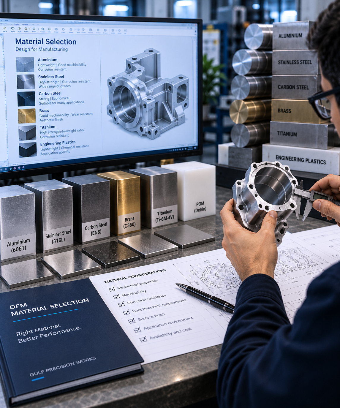
Engineer reviewing engineering material options for a CNC machined component during DFM assessment
Material Review

Material Selection & Machinability

Review required grade, condition, hardness, machinability and application-specific material requirements before defining the manufacturing route.
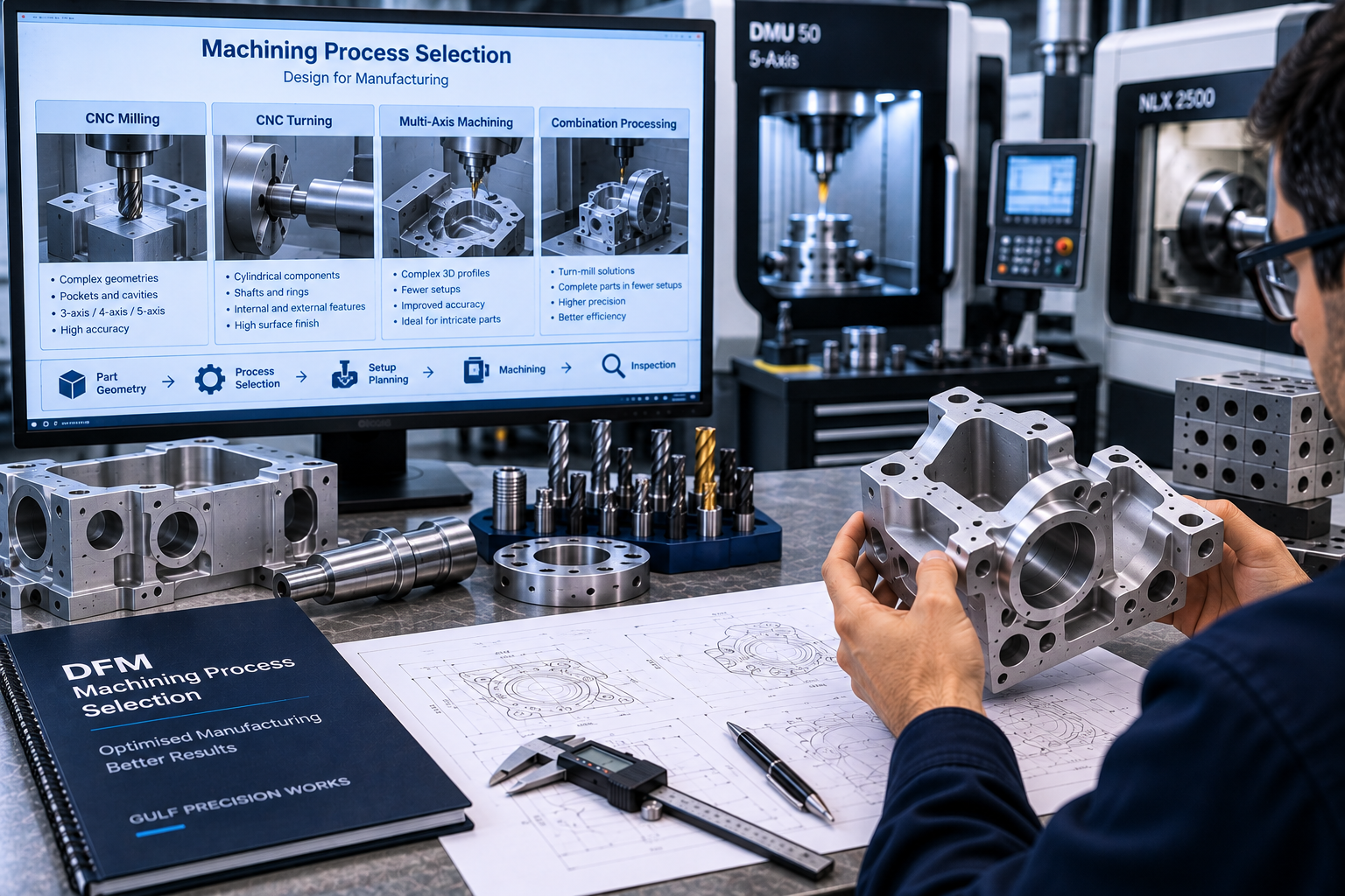
CNC milling and turning process planning reviewed for component geometry and manufacturing requirements
Process Strategy

Milling, Turning & Setup Planning

Component geometry can influence whether milling, turning, multi-axis machining or a combination of operations is appropriate.
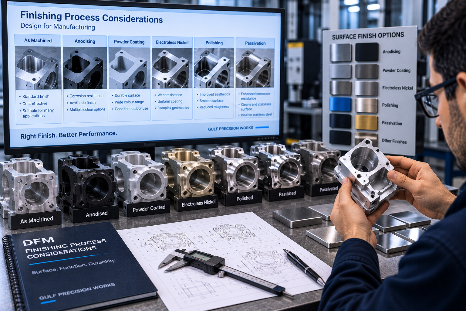
CNC machined component reviewed for finishing surface requirements and downstream manufacturing considerations
Downstream Requirements

Finishing & Post-Machining Considerations

Surface finish, coating, treatment, assembly and inspection requirements may affect the manufacturing sequence and final component definition.

Material Grade & Condition

Define the actual engineering material requirement.

Geometry Suitable Machining Route

Match component form with practical machining processes.

Surface Finish & Treatment

Consider final surface requirements early in the review.

Quality Inspection Requirements

Define critical verification and documentation needs.

Prototype to Production Readiness

Use DFM Feedback to Build a Clearer Path Toward Production.

DFM is most useful when it is applied before the design becomes difficult to change. Prototype machining, dimensional verification and engineering feedback can help clarify the component definition before repeat production requirements are established.

01
Input

Design Definition

Start with the latest CAD model, drawing, material specification and functional requirements.

02
Review

DFM Assessment

Review geometry, tool access, tolerances, materials, workholding and machining considerations.

03
Prototype

Initial Machining

Manufacture an initial component or batch using the agreed design and machining approach.

04
Verify

Inspection & Functional Review

Review agreed dimensions, critical features and functional findings from the prototype stage.

05
Control

Revision Confirmation

Incorporate approved engineering changes and confirm the drawing revision intended for production.

06
Production

Manufacturing Readiness

Move forward with a clearer component definition, inspection requirement and repeat manufacturing scope.

Gate 01 Engineering Approval

Proposed design changes remain subject to approval by the responsible engineering authority.

Gate 02 Prototype Verification

Confirm the agreed dimensional and functional requirements before committing to repeat manufacture.

Gate 03 Controlled Revision

Production should reference the approved drawing revision and agreed manufacturing requirements.

Typical DFM Improvements

Small Design Changes Can Create More Practical Manufacturing Conditions.

DFM review does not mean redesigning a component simply to make machining easier. It identifies features that may deserve engineering discussion where a practical adjustment could support machining access, inspection, process stability or clearer manufacturing definition without compromising functional intent.

Initial Design Condition
→
DFM Review Consideration
Pocket Geometry Very Deep Internal Pocket

Deep cavities may require extended tooling and can create difficult access conditions depending on component geometry.

→
Review
DFM Consideration Review Depth Against Functional Need

Where engineering intent allows, pocket depth or access geometry may be reviewed to support a more practical cutting-tool arrangement.

Internal Corner Sharp Internal Corner

Standard rotating cutting tools naturally create a radius at internal corners.

→
Review
DFM Consideration Define a Practical Internal Radius

Where a sharp corner is not functionally necessary, an appropriate radius can be considered during engineering review.

Tolerance Tight Tolerances Applied Broadly

Applying the same restrictive tolerance to non-critical features can introduce unnecessary manufacturing and inspection requirements.

→
Review
DFM Consideration Control the Features That Matter

Critical dimensions can remain tightly controlled, while other requirements can be clarified according to functional need.

Tool Access Feature Hidden Behind Other Geometry

Restricted tool approach may require specialised tooling, additional setups or a different machining strategy.

→
Review
DFM Consideration Review Orientation or Access

Where permitted by the design, feature position or surrounding geometry may be reviewed to improve direct machining access.

Wall Structure Thin Unsupported Wall

Thin sections may require special consideration for workholding, machining sequence and dimensional stability.

→
Review
DFM Consideration Review Structural Requirement

Wall thickness and support geometry can be reviewed against functional requirements and the intended manufacturing process.

Thread Definition Incomplete Thread Requirement

An unclear callout can leave thread size, depth, engagement or inspection expectations open to interpretation.

→
Review
DFM Consideration Fully Define the Threaded Feature

Confirm specification, depth, access and any inspection requirement before machining begins.

Geometry Clearer Tool Access

Review difficult features before machining strategy is fixed.

Definition Better Drawing Clarity

Reduce ambiguity around critical manufacturing requirements.

Process More Practical Planning

Align geometry, setups and process requirements earlier.

Production Stronger Revision Control

Move forward using an approved manufacturing definition.

Design for Manufacturing FAQs

Common Questions About DFM for CNC Machining.

DFM review helps clarify manufacturing considerations before machining begins. These questions explain how the process fits into prototype, engineering and production projects at Gulf Precision Works.

What is Design for Manufacturing in CNC machining?

Design for Manufacturing, or DFM, is the review of a component's geometry, tolerances, material, machining access, workholding and other manufacturing considerations before production begins. The objective is to identify issues that may benefit from clarification or engineering review before machining.

When should a DFM review be carried out?

DFM is most useful before the design is fully frozen, especially before prototype machining, production transfer or repeat manufacturing. Early review provides more opportunity to clarify geometry and manufacturing requirements before the process is established.

What information should I provide for a DFM review?

Provide the latest CAD model and technical drawing, together with the required material, quantity, critical dimensions, surface requirements and any relevant inspection or documentation requirements. Functional context can also help clarify which features are important to the design.

Will GPW change my component design?

DFM feedback may identify features that deserve engineering discussion, but GPW should not be considered the final design authority unless that responsibility has been explicitly defined. Any design change should be reviewed and approved by the responsible engineering authority before the drawing or CAD revision is updated.

Can DFM help with tight tolerance components?

Yes. DFM review can help identify which dimensions and geometric controls are functionally critical, how those requirements relate to machining strategy, and what inspection approach may be appropriate. Final tolerance requirements remain governed by the approved engineering drawing.

Does DFM include material selection?

Material can form part of the manufacturability review. Factors such as grade, condition, machinability, hardness, corrosion resistance and downstream finishing may influence manufacturing planning. Final material selection should follow the project's engineering and functional requirements.

Can DFM support prototype-to-production projects?

Yes. DFM review can be used before prototype machining, followed by prototype verification and approved engineering revision before repeat production. This can help create a clearer manufacturing definition for later production requirements.

Does a DFM review guarantee lower manufacturing cost?

No. DFM can identify manufacturing considerations that may affect tooling, setups, machining time, inspection or process complexity, but project cost depends on the final geometry, material, quantity, tolerances and complete manufacturing scope.

Have a Component That Needs Manufacturability Review?

Send the latest CAD model, drawing, material requirement and expected quantity so the manufacturing scope can be reviewed before machining begins.

Submit Your DFM Enquiry
Engineer reviewing CAD model technical drawing and CNC machined component before production

Start Your DFM Review

Review Manufacturability Before CNC Machining Begins.

Share the latest design definition before committing the component to prototype or production machining.

Send your CAD model, technical drawing, material specification, expected quantity, critical features and relevant quality requirements to Gulf Precision Works. We can review the manufacturing scope and identify practical DFM considerations for CNC machining projects across the UAE and wider Gulf region.

Design CAD Model
Definition Latest Drawing
Material Grade & Condition
Production Quantity / Forecast
Quality Critical Requirements
Design → Review → Refine → Manufacture Geometry · Tool Access · Tolerances · Materials · Setups · Inspection · Production Readiness