Precision CNC Manufacturing

CNC Machining Tolerances for Precision Components

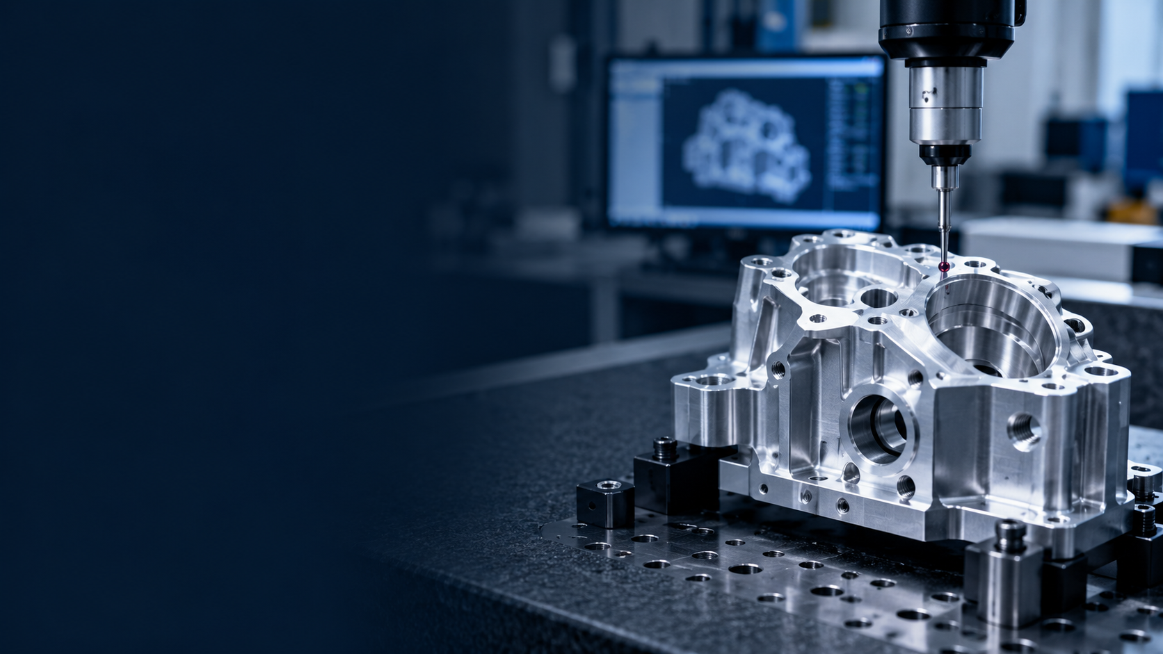
Precision CNC machining for engineered components requiring controlled dimensions, repeatability and drawing-defined tolerances across prototype and production requirements in the UAE and international markets.

Dimensional Control
Inspection & Verification
Drawing-Based Manufacturing
Precision. Performance. Reliability.

Tolerance Capabilities

Precision Manufacturing Built Around Your Drawing

Machining tolerances depend on component geometry, material, feature size, manufacturing process and inspection requirements. Our manufacturing approach begins with reviewing these requirements before production.

Dimensional Tolerances

Controlled machining of critical lengths, widths, diameters and component features according to drawing requirements.

Geometric Tolerances

Manufacturing support for drawing-defined form, orientation and positional requirements on precision engineering components.

Hole & Bore Control

Precision machining of holes, bores and mating features requiring controlled dimensions and functional relationships.

Repeatability

Process control supporting dimensional consistency across repeat component manufacturing and production requirements.

Tolerance requirements are component-specific.

Critical dimensions should be identified on the engineering drawing so that geometry, material, machining strategy and inspection requirements can be reviewed before production.

Tolerance Reference

Typical CNC Machining Tolerance Considerations

Tolerance requirements vary according to material, component geometry, feature size and application. The manufacturing and inspection approach should therefore be based on the requirements defined in your engineering drawing.

  • Drawing-defined dimensional requirements
  • Component-specific manufacturing review
  • Inspection matched to critical features
Discuss Your Requirements
Feature Typical Requirement Manufacturing Consideration
Linear Dimensions Drawing specified Feature size, accessibility and machining strategy
Diameters Drawing specified Turning, milling or boring process
Hole Sizes Drawing specified Drilling, reaming or precision boring
Flatness Application specific Component geometry, setup and datum strategy
Parallelism Application specific Datum selection and machining strategy
Position (GD&T) Drawing / GD&T specified Datum structure and suitable inspection method
Surface Finish Drawing specified Material, tooling and machining process
Need tighter tolerances?

Critical dimensions should be identified on your engineering drawing. Our team can review the component geometry, material, machining requirements and inspection considerations before production.

Engineering Insights

What Affects Achievable CNC Machining Tolerances?

Several factors influence the achievable tolerance on a machined component. Understanding these factors helps optimise component design, manufacturing strategy and inspection requirements.

Discuss Your Requirements
01.

Material

Different materials respond differently to machining forces, heat and dimensional stability.

02.

Component Geometry

Thin walls, deep pockets and complex geometries can influence achievable dimensional accuracy.

03.

Feature Size

Very small, deep or slender features may require specialised tooling and machining strategies.
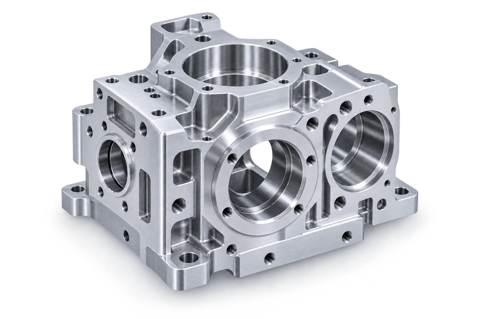
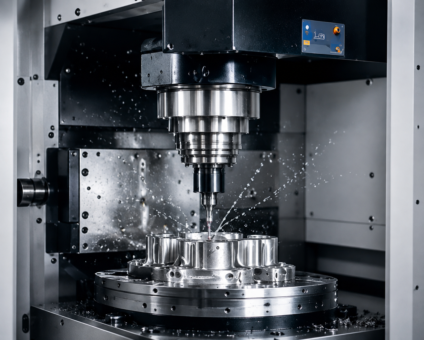
Precision CNC machined component illustrating factors affecting machining tolerances
04.

Machine Setup

Workholding, datum selection and the number of setups can influence dimensional control.

05.

Surface Finish

Surface-finish requirements can affect tooling, machining parameters and final dimensions.

06.

Inspection Method

Critical dimensions must be compatible with an appropriate and repeatable measurement method.

Engineering Review Matters

The tightest achievable tolerance is not a single fixed value for every CNC-machined part. Component geometry, material, manufacturing process and inspection method should be reviewed together against the functional requirements of the engineering drawing.
Precision Machining

Engineered for Critical Component Features

From simple to complex components, our CNC machining capabilities support precision features manufactured to drawing-defined dimensional and functional requirements.

01

Precision Bores

Controlled bore dimensions and mating surfaces for components requiring accurate internal features and functional fits.

02

Hole Patterns

Accurate feature positioning and controlled hole patterns based on drawing-defined dimensions and datum requirements.

03

Mating Features

Dimensional control for functional features designed to interface, locate or assemble with related components.

04

Critical Diameters

Precision machining and turning of functional diameters requiring controlled size and dimensional consistency.

05

Flat & Parallel Surfaces

Controlled machining of datum, mounting and mating surfaces according to component drawing requirements.

06

Complex Geometries

Multi-surface CNC machining for components with demanding geometry, multiple features and complex machining requirements.

Have a Component With Critical Features?

Send your engineering drawing, material, tolerance and quantity requirements for manufacturing review.

Discuss Your Component
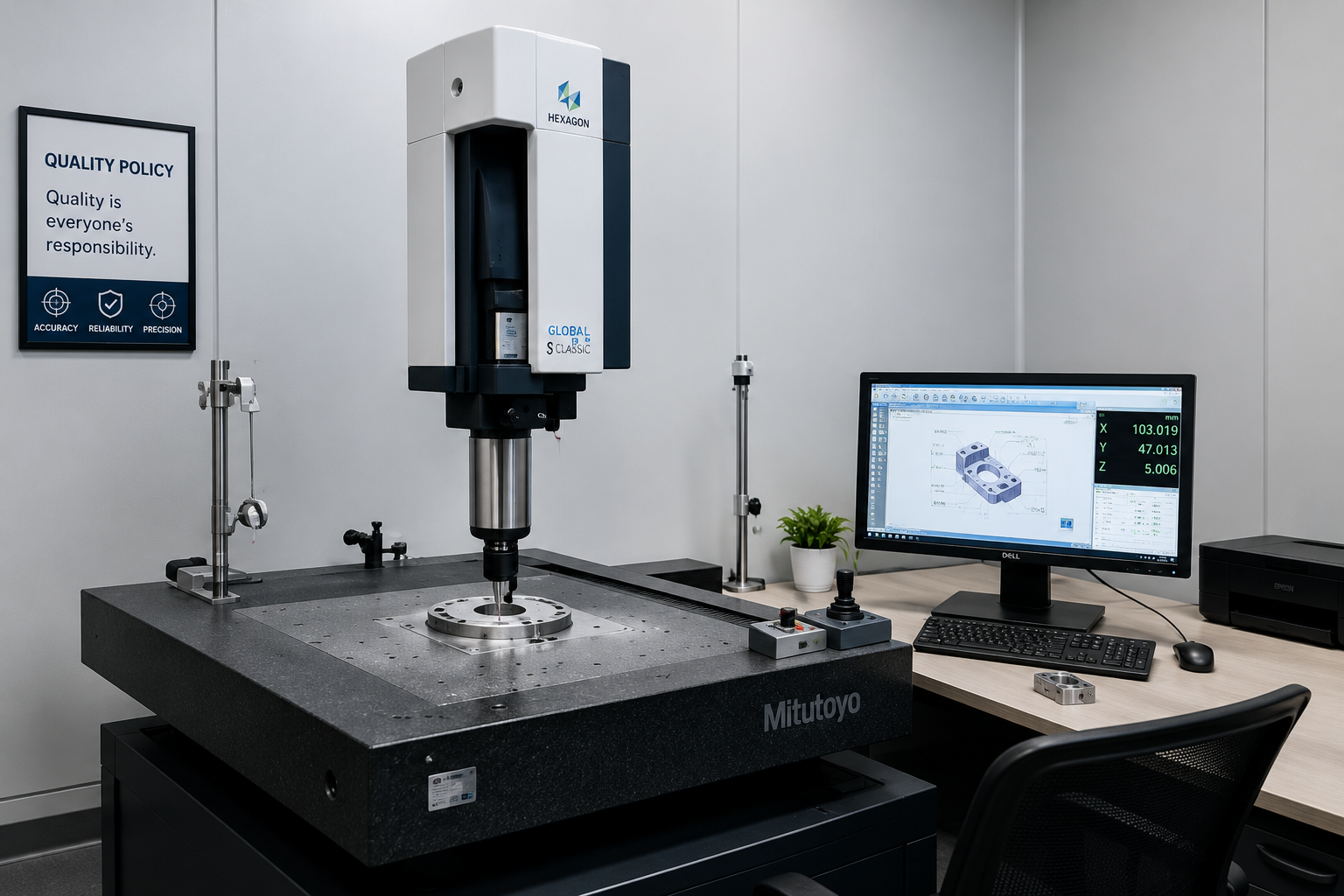
CMM inspection of a precision CNC machined component for dimensional verification
Quality Verification Dimensional Inspection & Measurement

Inspection & Verification

Precision Is Verified, Not Assumed

Dimensional inspection is an essential part of precision CNC manufacturing. Measurement methods are selected according to component geometry, critical features and the requirements defined in the engineering drawing.

Dimensional Inspection

Verification of specified dimensions and critical component features against drawing requirements.

CMM Verification

Coordinate measurement for suitable complex features, positions and component geometries.

In-Process Inspection

Measurement during manufacturing supports process control and dimensional consistency.

Inspection Documentation

Measurement records and inspection documentation can support project verification and traceability.

Inspection requirements should be defined according to component function, drawing specifications and project requirements.
Engineering Guidance

Specify Tolerances Where They Matter

Applying very tight tolerances to every dimension can increase machining complexity, inspection requirements and manufacturing cost. A well-defined engineering drawing identifies the features that are critical to component function while allowing practical tolerances elsewhere.

01

Identify Critical Features

Clearly identify dimensions and features that directly affect component function, assembly, alignment or performance.

02

Define Datums

A clear datum structure helps establish how component features relate to one another during machining and inspection.

03

Avoid Unnecessary Tight Tolerances

Apply tighter requirements where function demands them rather than across dimensions that do not require the same level of control.

04

Provide Complete Drawings

Include dimensions, tolerances, material, surface-finish requirements, datums and applicable GD&T information where required.

Design Review Before Manufacturing

Send us your engineering drawing, material, quantity and tolerance requirements. The component can then be reviewed in relation to machining strategy, critical features and inspection requirements.

Discuss Your Drawing

Precision CNC Manufacturing

Have a Component With Critical Tolerance Requirements?

Send us your engineering drawing, material, quantity, dimensional tolerances and inspection requirements. Our team can review the component requirements before manufacturing.

  • Engineering Drawing Review
  • Tolerance & Manufacturability Review
  • Prototype & Production Support
Drawing-Based Review Requirements assessed from your component drawing
Inspection Planning Measurement aligned with critical features
UAE & International Manufacturing support for engineering projects